Have you ever looked at a complex industrial diagram and wondered what all those lines, symbols, and instruments mean? If so, you’re not alone.
Understanding P&ID meaning is essential for anyone working in engineering, process industries, or even for curious students exploring industrial systems.
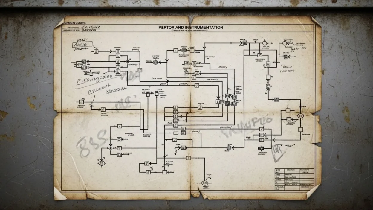
A Piping and Instrumentation Diagram (P&ID) is more than just a technical drawing it’s a detailed map of how equipment, pipes, and control instruments work together to make a process function smoothly.
If you’re designing a chemical plant, maintaining machinery, or learning the basics of process engineering, knowing how to read and interpret a P&ID can save time, prevent mistakes, and ensure safety.
In this guide, we’ll break down what P&ID stands for, its key components, and how to understand these diagrams, giving you the confidence to navigate them like a professional.
What Does P&ID Mean?
The term P&ID stands for Piping and Instrumentation Diagram, and it’s one of the most important tools in process engineering and industrial design. At its core, a P&ID is a detailed schematic that illustrates how piping, equipment, and instruments connect and interact within a system. Unlike a simple flowchart, a P&ID provides precise information about every component, including valves, pumps, tanks, sensors, and controllers.
Breaking down the term:
- Piping refers to the network of pipes that transport fluids, gases, or chemicals from one part of the system to another. Piping lines are drawn with specific styles and symbols to indicate the type of pipe, flow direction, and sometimes the material.
- Instrumentation includes all the devices used to measure, control, and monitor the process. This can be pressure gauges, flow meters, temperature sensors, and control valves. Instrumentation ensures the system operates efficiently and safely.
- Diagram signifies that all this information is presented graphically, making it easier for engineers, operators, and technicians to understand complex processes at a glance.
Understanding P&ID meaning is not just about memorizing symbols. It’s about interpreting the relationships between different parts of the system and how they work together to achieve the desired process outcome. Engineers rely on P&IDs for designing systems, troubleshooting issues, planning maintenance, and ensuring safety standards are met.
Importance of P&ID in Industry
Understanding the meaning of P&ID is not just academic—it plays a critical role in real-world industrial operations. A Piping and Instrumentation Diagram (P&ID) serves as a blueprint for designing, operating, and maintaining complex systems in industries such as chemical manufacturing, oil and gas, water treatment, and power generation.
One of the primary benefits of a P&ID is clarity in communication. Engineers, operators, and technicians use these diagrams to understand the layout of equipment, the flow of materials, and the placement of control instruments. This clarity reduces errors during construction, operation, and maintenance.
P&IDs are also essential for ensuring safety. By showing all process connections, control points, and safety devices like relief valves, these diagrams help prevent accidents and allow teams to respond quickly during emergencies. For example, in a chemical plant, a clear P&ID ensures that operators know which valves to shut off during a leak or pressure spike.
Moreover, P&IDs aid in process optimization and troubleshooting. Engineers can identify bottlenecks, inefficiencies, or potential failure points by studying the diagram. They also make it easier to plan maintenance schedules, replacements, or upgrades without disrupting the entire system.
In short, knowing the P&ID meaning and how to read these diagrams is crucial for anyone involved in industrial processes. It saves time, improves safety, and ensures systems operate efficiently, making it an indispensable tool in modern engineering.
Key Components of a P&ID
A P&ID diagram is packed with symbols and lines, each representing a critical part of an industrial system. Understanding the key components of a P&ID is essential for interpreting how the system works and ensuring smooth operations.
1. Pipes:
Pipes are the backbone of any process system. They transport fluids, gases, or chemicals between equipment. P&ID diagrams use different line types and thicknesses to indicate pipe size, flow direction, and sometimes material type. Arrows often show the direction of flow.
2. Valves:
Valves control the flow of materials within the pipes. Common types include gate valves, globe valves, ball valves, and check valves. Each valve type has a unique symbol, making it easy to identify its function on the diagram.
3. Equipment:
This includes tanks, pumps, compressors, heat exchangers, and reactors. Equipment symbols help engineers locate devices and understand their interaction with the rest of the system.
4. Instrumentation:
Instruments monitor and control the process. Pressure gauges, flow meters, temperature sensors, and controllers are standard examples. Symbols often include tags to show what the instrument measures and its connection to control systems.
5. Miscellaneous Symbols:
P&IDs may also include fittings, flanges, safety devices, and other accessories, each with its own symbol for easy identification.
How to Read a P&ID Diagram
Once you understand the P&ID meaning and its key components, the next step is learning how to read a P&ID diagram. While these diagrams may seem complex at first, following a systematic approach makes them much easier to interpret.
1. Identify the Process Flow:
Start by locating the main process lines. Arrows indicate the direction of flow, helping you understand how materials move through the system from start to finish.
2. Recognize Equipment Symbols:
Identify the major equipment such as tanks, pumps, compressors, and heat exchangers. Knowing what each symbol represents allows you to visualize the physical system.
3. Follow the Piping Network: Examine the connections between equipment. Look for pipe types, sizes, and flow directions. Understanding the pipe network helps in tracing the movement of materials accurately.
4. Locate Valves and Controls:
Valves control flow, pressure, and safety, while instruments monitor the process. Check each symbol carefully and note the control points. Tags often indicate what the device measures or controls.
5. Observe Additional Details:
Safety devices, flanges, and fittings are also important. Don’t skip these, as they play a crucial role in the system’s operation and maintenance.
6. Cross-Reference with Legends or Notes:
Most P&IDs include a legend explaining symbols and abbreviations. Use it to clarify any unfamiliar elements.
P&ID vs PFD (Process Flow Diagram)
When learning about P&ID meaning, it’s common to encounter another diagram called a Process Flow Diagram (PFD). While both are essential in engineering, they serve different purposes and provide different levels of detail.
A PFD is a high-level diagram that shows the main equipment and the overall flow of materials in a process. It provides a simplified view of the system, highlighting major units like reactors, pumps, and heat exchangers, along with primary flow paths. PFDs are mainly used for conceptual design, process analysis, and initial planning.
In contrast, a P&ID is far more detailed. It includes not only the equipment and flow lines but also piping details, valve types, instruments, control systems, and safety devices. A P&ID shows exactly how each component interacts, making it essential for operation, maintenance, and safety compliance.
Key differences:
- Detail Level: PFDs are high-level, P&IDs are highly detailed.
- Purpose: PFDs are for design and overview; P&IDs are for operation, troubleshooting, and construction.
- Symbols: PFDs use simpler symbols; P&IDs use standardized symbols for valves, instruments, and equipment.
- Users: Engineers use PFDs for planning; operators, technicians, and process engineers rely on P&IDs for day-to-day work.
Understanding the difference between PFD and P&ID helps professionals communicate clearly and ensures that processes are designed, implemented, and maintained safely. When learning about P&ID diagrams, recognizing this distinction is crucial for accurate interpretation and practical application.
Common P&ID Standards
Understanding P&ID meaning goes beyond symbols and diagrams—it also involves following established standards. P&ID standards ensure consistency, clarity, and safety across industries worldwide. These standards define how symbols are drawn, how instruments are labeled, and how diagrams are organized, making it easier for engineers and operators to interpret them correctly.
One widely used standard is ANSI/ISA (American National Standards Institute / International Society of Automation). It provides detailed guidelines for instrumentation symbols, control loops, and labeling conventions, helping engineers create diagrams that are universally understandable.
Another important standard is ISO 10628, an international standard for PFDs and P&IDs. It covers the graphical representation of process systems, including piping, equipment, and control devices. Many multinational companies follow ISO standards to ensure diagrams are consistent across plants and countries.
ASME (American Society of Mechanical Engineers) also provides standards related to piping symbols and diagram conventions. Following ASME ensures that diagrams are accurate, which is critical for safety, maintenance, and regulatory compliance.
In addition to these, some industries or companies develop their own internal P&ID standards to meet specific operational requirements. Regardless of the source, the key is consistency: using standardized symbols, labeling, and notation prevents confusion, reduces errors, and improves communication between engineers, operators, and maintenance teams.
By following these P&ID standards, anyone reading a diagram—from beginners to experienced engineers—can accurately interpret the system, ensuring safety, efficiency, and effective collaboration. Standards are the backbone of clear and reliable P&ID diagrams.
Tips for Beginners Working with P&ID
If you are new to P&ID meaning and diagrams, it can feel overwhelming at first. However, with the right approach, beginners can quickly become comfortable reading and interpreting these essential engineering tools. Here are some practical tips to get started.
1. Learn Common Symbols:
Start by memorizing the most frequently used symbols for equipment, valves, and instruments. Understanding these symbols is the first step toward reading any P&ID diagram accurately.
2. Use a Legend:
Most P&ID diagrams include a legend explaining all symbols and abbreviations. Always refer to it when encountering unfamiliar elements. This ensures you interpret the diagram correctly without guessing.
3. Follow the Process Flow:
Begin by tracing the main flow lines from start to finish. This helps you understand how materials move through the system and how different components interact.
4. Break It Down:
Don’t try to understand the entire diagram at once. Focus on one section or system at a time—pumps, piping, or instrumentation. Gradually, you’ll see how everything connects.
5. Practice with Examples:
Download sample P&ID diagrams or use software like AutoCAD or SmartPlant P&ID to practice. Hands-on experience makes concepts easier to grasp.
6. Ask for Guidance:
Work with experienced engineers or instructors who can explain tricky parts and share practical insights. Real-world explanations often make diagrams clearer than textbooks.
FAQs About P&ID Meaning
1. What does P&ID stand for?
P&ID stands for Piping and Instrumentation Diagram. It is a detailed graphical representation of a process system, showing how equipment, piping, valves, and instruments interact to control and transport materials.
2. Why is a P&ID important?
P&IDs are crucial for design, operation, and maintenance of industrial systems. They provide clarity, help prevent errors, ensure safety, and allow engineers and operators to communicate effectively.
3. What is the difference between a PFD and a P&ID?
A Process Flow Diagram (PFD) shows the overall process flow and major equipment in a simplified way. A P&ID is more detailed, including piping, valves, instruments, and safety devices. P&IDs are used for operations and maintenance, while PFDs are mainly for conceptual design.
4. What are common P&ID symbols?
P&ID symbols represent pipes, valves, pumps, tanks, sensors, and control devices. Each symbol is standardized according to ANSI, ISA, ISO, or company-specific standards to ensure clear communication.
5. How can beginners learn to read P&ID diagrams?
Start by learning basic symbols, follow the process flow, practice with sample diagrams, and refer to legends. Using software tools and guidance from experienced engineers can accelerate learning.
6. Are P&ID standards the same worldwide?
While many symbols follow international standards like ISO 10628 and ANSI/ISA, some industries or companies have internal standards. Consistency is key for clarity and safety.
Conclusion
Understanding the meaning of P&ID is essential for anyone involved in engineering, process industries, or industrial maintenance.
A Piping and Instrumentation Diagram (P&ID) is more than just a technical drawing it is a comprehensive map of how equipment, piping, valves, and instruments work together to ensure a system operates safely and efficiently.
By learning how to read P&ID diagrams, recognizing symbols, and following process flows, engineers, students, and technicians can prevent errors, optimize operations, and communicate effectively across teams.
P&IDs are also standardized through ANSI, ISA, ISO, and ASME guidelines, making them universally understandable in professional settings.
Beginners can start by focusing on key components, practicing with sample diagrams, and seeking guidance from experienced professionals.
With consistent practice, reading and interpreting P&IDs becomes intuitive, bridging the gap between theory and real-world industrial applications.
Ultimately, mastering P&ID diagrams is a critical skill for anyone looking to excel in modern engineering environments.